Touch-Sensing Skins for Soft Robots
On this page:
Our strain sensors are made from exfoliated graphite (EG) mixed into a latex elastomer (natural rubber). The EG particles are electrically conductive, and above 15 wt% EG, the composite becomes conductive. Charge is transported through the material by "percolation" - moving among the conductive particles. These sensors are piezoresistive: when the elastomeric composite is stretched, the interparticle distance changes, and the electrical resistance of the material changes. In tension, the resistance change is linear with strain (ΔL/L, where ΔL is the change in length and L the original length).
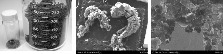
Exfoliation of Graphite EG is produced from graphite in a microwave oven. The graphite expands perpendicular to the sheet orientation. Before and after photos are shown on the left. The expanded graphite consists of lightweight, wormlike particles, as shown in the center image, consisting of loosely-attached sheets. These are separated by sonication, which is done in a fluid. The result is a mixture of single and multi-layer graphene flakes, as shown on the right.
Spray Coating
For further information, see: M. Kujawski, J. D. Pearse, and E. Smela, "Elastomers filled with exfoliated graphite as compliant electrodes," Carbon, 48 (9), 2409-2417 (2010). M. Kujawski, J. Pearse, and E. Smela, "Graphite/PDMS stretchable electrodes for dielectric elastomer actuators," Electroactive Polymer Actuators and Devices (EAPAD) XII, SPIE Symposium on SPIE Smart Structures and Materials and Nondestructive Evaluation and Health Monitoring, San Diego, (SPIE), edited by Y. Bar-Cohen, p. accepted (7-11 March, 2010). Sensing Flapping Wing Deformation There is an effort at UMD by S. K. Gupta and
Hugh Bruck
to develop miniature air vehicles (MAVs) with flapping wings, the robo-raven.
Monitoring the deformation of the wing during flight would allow these vehicles to adapt thier flight in windy conditions. We demonstrated that this could be done using our minimally invasive compliant piezoresistive sensors. The gauges are thin, compliant, and light enough to measure deformations of the flexible wings. In tension the static sensitivity is linear and has a gauge factor of 28; in compression, the gauge factor is smaller, −5.
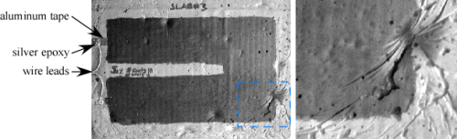
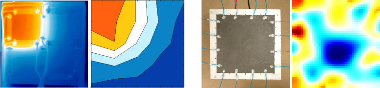
J. Wissman, A. Perez-Rosado, A. Edgerton, B. M. Levi, Z. N. Karakas, M. Kujawski, A. Philipps, N. Papavizas, D. Fallon, H. A. Bruck, and E. Smela, "New compliant strain gauges for self-sensing dynamic deformation of flapping wings on miniature air vehicles," Smart Mater. Struct., 22 085031 (2013). Sensing skins have been made from two perpendicular arrays of strips as well as continuous areas. Sensing Array Below is an area sensor constructed from two arrays of row and column electrodes on either side of a latex sheet (orange), resting on a foam substrate (yellow). Strains were imaged using digital image correlation (DIC), a technique developed by Hugh Bruck in which the positions of markers on the surface (speckles in the rightmost figure below) are tracked optically. This work was done by James Tigue.
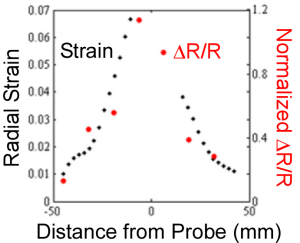
The sensing array can accurately locate the position of a load on the surface, at the center, and the resistance readings
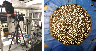
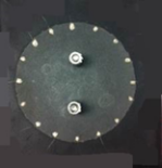
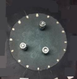
correspond to the strain, as shown on the right. Another approach to localizing touch over an area is to use electrical impedance tomography (EIT). With this technique, electrical connections are made only at the perimeter of the sensing area. Current is injected into one adjacent pair, and the voltage difference between every other adjacent pair around the perimeter is measured. Then the current-injecting pair is rotated one position, and the process is repeated. An algorithm then reconstructs the spatial resistance map in the interior that produced these measurements. This is a so-called inverse problem. The figures below show a circular EG/latex sensing area with 16 evenly spaced electrodes at the perimeter, with the wires attached by silver epoxy. The wires are connected to a data acquisition system, and a Matlab program processes the data. In the left pair of figures, two weights were placed on the sensor, and the algorithm reconstructed those two areas. In the right pair, there were three objects, which again appear in the EIT image. This work was done by Ying Chen.
For further information, see: H. A. Bruck, E. Smela, M. Yu, J. Tigue, O. Popkov, G. Ocel, and Y. Chen, "Compliant artificial skins to enable robotic sensing and training by touch," Proc. 2014 Annual Conference on Experimental and Applied Mechanics, (Springer, Society for Experimental Mechanics), vol. 7, edited by K. Zimmerman (2015). The EG/latex composite films can be used not only to sense strain, but also to sense temperature. This can be done with an array of calibrated sensors. The left image shows a heat map from an IR camera under a grid of 12 sensing strips that is heated to 55 oC (orange) in the upper left corner and is at room temperature (blue) elsewhere. Three of the strips can be clearly seen in the heated area, with their wire leads. Just to the right of that is the temperature map reconstructed from the 12 sensor readings. The map shows the location of the heat source as well as the correct temperature. This work was done by Liz Sauerbrunn.
In addition, continuous, distributed temperature sensing can be achieved using electrical impedance tomography (EIT) to reconstruct a thermal image. In this configuration, the sensing area is contacted by 16 electrodes around the edge. For the rightmost image, a Peltier element set to cool to 7 oC was placed in the center of the sensor. (The varations outside of the cold central area are artifacts of the EIT reconstruction; we are working to improve the algorithms.) This work was done by Ying Chen. For further information, see: E. Sauerbrunn, Y. Chen, J. Didion, M. Yu, E. Smela, and H. A. Bruck, "Thermal imaging using polymernanocomposite temperature sensors," Phys. Stat. Sol. (available online - not yet in print) (2015).
Page last updated: August 10, 2015 |
|
|

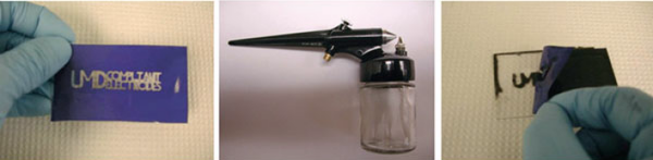 The strain sensors are applied as thin films by spray painting (or alternatively brush coating) over a stencil.
The stencil, here made of tape, is removed after the sensing paint is no longer fluid.
The strain sensors are applied as thin films by spray painting (or alternatively brush coating) over a stencil.
The stencil, here made of tape, is removed after the sensing paint is no longer fluid.
 The sensors are readily coated onto virtually any surface. The figures show strain sensors on concrete (right) and gloves (left).
Note how the paint conformally coates the surface. Here, wires are attached using silver epoxy and/or metal tape.
The sensors can detect when contact is made with an object. This work was done by
The sensors are readily coated onto virtually any surface. The figures show strain sensors on concrete (right) and gloves (left).
Note how the paint conformally coates the surface. Here, wires are attached using silver epoxy and/or metal tape.
The sensors can detect when contact is made with an object. This work was done by
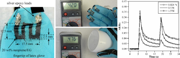
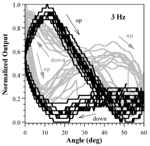
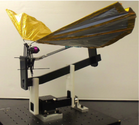 The left figure shows the MAV mounted on a load cell. The right figure shows the normalized resistance change as a function of the angle of the wing during flapping at 3 Hz in black, and the force generated during the flapping in gray. The double peak, seen in both signals, is associated with optimal lift.
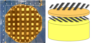


©2013